Manufacturing cases & product examples
See what the
details became.
Our manufacturing cases document implemented tooling and molded parts. Engineering reviews are separate: analysis of real reference products and how we would approach a comparable project.
Explore molded parts and tooling decisions: precision interfaces, zero-draft enclosures, perforated covers, linked buttons, soft overmolding and distinctive surfaces. Find the features your own product needs to get right.
4 project and product examples

Three ink paths.
One integrated mold.
A cartridge housing with closely spaced outlets and a chip interface. Internal and external slides plus angled core withdrawal replaced a two-mold approach with one production mold.
Explore the mold in 5 steps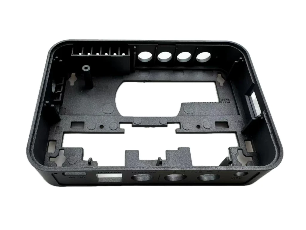
Zero draft.
Four sides that release.
A fixed exterior requirement led to four side sliders. Peripheral ribs support and locate the mating panel alongside four screws.
Explore assembly & appearance
A rigid interface.
A softer working surface.
Component photographs, tooling and colored production batches connect overmolding questions to physical manufacturing.
Explore soft & rigid materials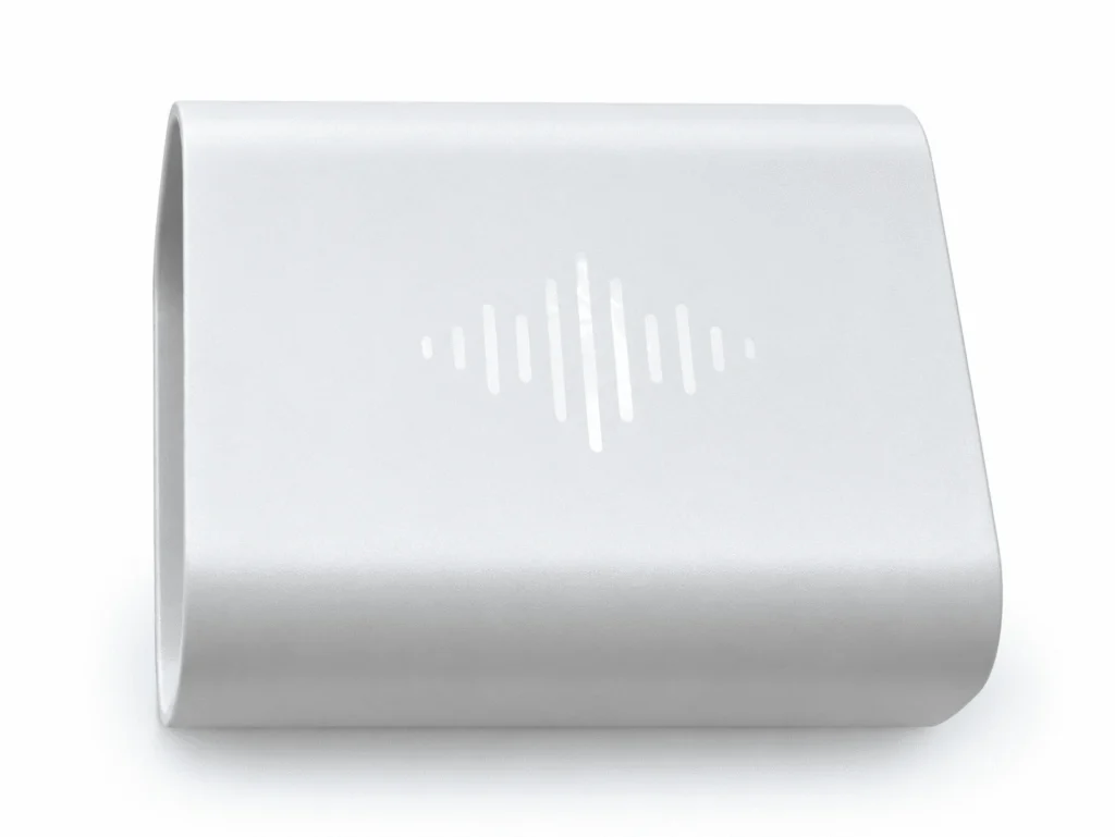
A bright pattern.
A subtle molded detail.
A real housing finish made through specialist laser processing of the mold. Explore the appearance decisions and the tooling investment behind it.
Explore surface finishYour product can be different.
The demands may be familiar.
A fixed connector position, a soft contact region, a visible finish or an interface that cannot drift: these are useful starting points for a manufacturing discussion. Share the feature that must work, together with the complete assembly.
Explore how we manufacture.
From engineering review and toolmaking to sample approval and repeat orders.
Manufacturing and part supplyMeet the factory behind the work.
Owner-led project coordination, virgin resin purchasing and tooling built for continued use.
Factory and quality principlesMore molded parts. More ways to recognize your project.
Different shapes.
Specific manufacturing questions.
These are photographs of parts we have made. Look beyond the outline: the hole pattern, button carrier, panel seat and closing edge each give the tool a different job. Here is what those features mean when we review a similar part with you.
An array of holes.
One continuous visible surface.
A long, rounded cover carries a dense hole pattern above a mounting flange. The mold must form the openings while the thin paths between them fill and the outside retains an acceptable appearance. The flange also has to meet the surrounding assembly.

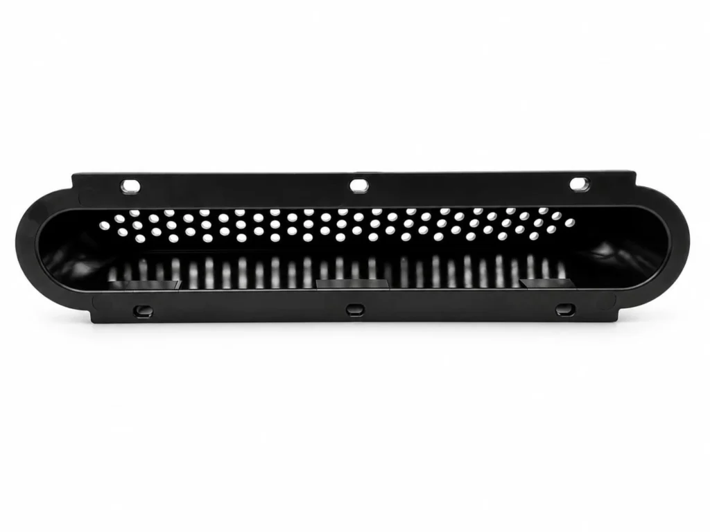


Keep openings usable
Review the steel shutoffs that form each hole, the permitted edge condition and the direction in which those features release. A hole that looks open in CAD can still need a clear flash acceptance reference.
Agree the visible result
Flow divides around the openings and joins again. Gate position and the accepted appearance of those meeting regions belong in the discussion before the tool is cut.
Protect the mounting fit
Review flange shape, mounting-hole locations and the surrounding part together. Cosmetic approval and assembled fit are separate checks.
The earlier grille DFM addresses the same perforated-cover feature pattern, including hole shutoffs and weld-line appearance. Its marked proposals describe the review stage. Read the hole and shutoff decision ↗
Four buttons share a carrier.
Each still has its own job.
The front carries four marked button heads. On the reverse, four stems transmit the press into the assembly; the connecting carrier and its locating holes position the set. Looking only at the visible buttons misses the geometry that determines how they work.
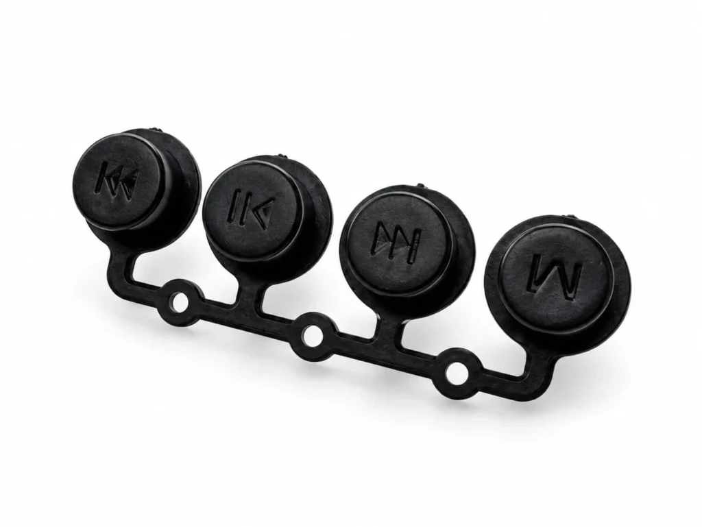
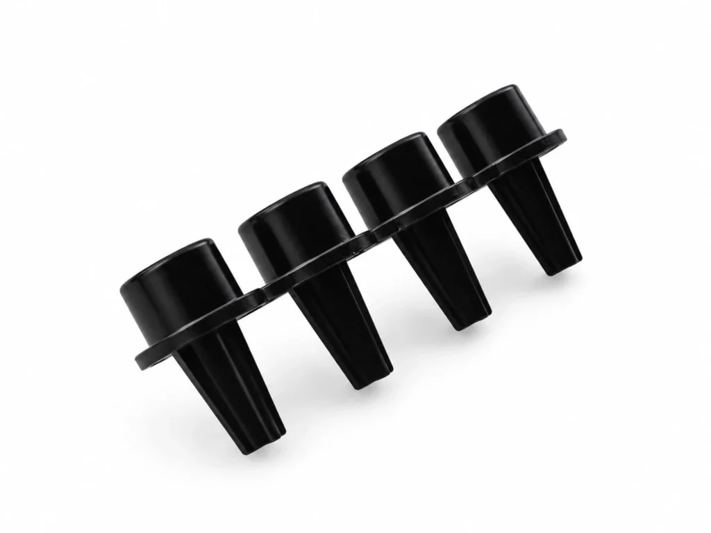
Locate the set
Identify which holes and surfaces locate the carrier relative to the cover and electronics. Review the full tolerance relationship, rather than four button diameters in isolation.
Preserve movement
Stem position, assembled height and clearance around each moving head need to be checked against the mating parts. The feel of the button is an assembly requirement.
Keep the gate out of the way
Choose and finish the gate with the installed button envelope in view. An acceptable mark on a free part can still interfere once the carrier is fitted.
The small-parts DFM shows the corresponding four-button arrangement. Its proposed 0.3 mm local change was intended to avoid gate-area interference; it is not a universal clearance or an allowable gate-remnant height. See the button gate review ↗
The ports, panel and board
must agree on position.
This enclosure combines side openings with a removable interface panel. Inside, button guides, locating features and screw supports share the same limited space. These details connect the visible housing to the components it has to hold.
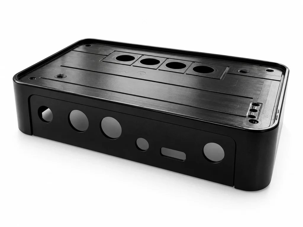
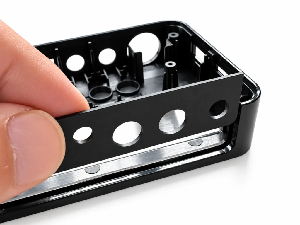
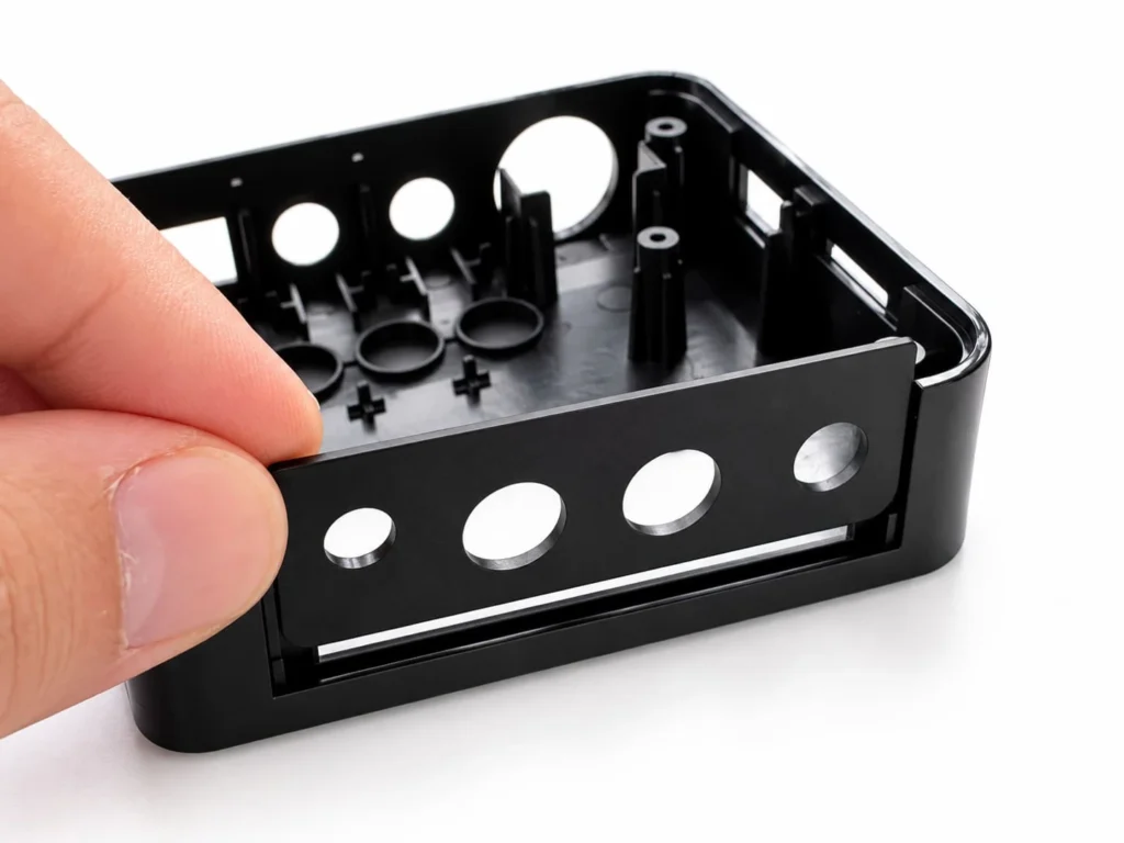

Start with the connector
Use the connector and board position to check the opening. Tool release, local clearance and the visible port edge need to be resolved around that functional location.
Define how the panel seats
Agree the closing edge, step and flushness reference. A separate panel creates another locating relationship; it does not remove the need to control the assembled surface.
Make the supports work together
Review screw engagement, bosses, ribs and board location as a system. Changing a boss wall without checking the screw or board can move the problem into assembly.
The decorative-cover DFM shows a related internal arrangement of button guides and locating features. We use that review to explain the engineering questions; it does not establish an identical revision for every component in this photographed assembly. Explore enclosure manufacturing ↗
Several openings.
A face that must stay coherent.
A circular pattern of small holes sits beside a larger opening and four control positions. The surrounding wall carries further interfaces. This is a useful example of a visible cover whose perforations and assembly references have to be considered together.

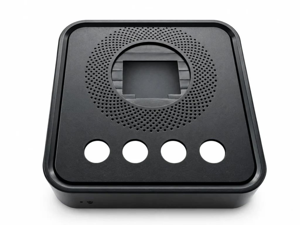
Review flow around interruptions
Multiple holes and the central opening divide the flow into narrow paths. Review filling and the location of flow joins before agreeing the cosmetic standard.
Keep the references connected
Button positions, the main opening and the closing rim should be checked against the same mating assembly. The outside outline alone is not a sufficient inspection reference.
Separate visual and functional approval
Agree acceptable hole edges and surface marks, then check the assembled fit and control movement. Photographs show the geometry; they do not substitute for those checks.
For a similar cover, send the mating geometry and identify the cosmetic face, functional holes and locating surfaces. Build a more useful RFQ ↗
A small enclosure.
A very visible closing edge.
A contrasting cover meets a compact black shell. Side openings and molded markings sit close to that joint. The product may be small, but its closing line, interface position and surface appearance are immediately visible.


Agree the assembled surface
Define the intended gap, step and support around the perimeter. Review the mating geometry before changing wall, rib or ejector details for moldability.
Respect the working openings
Check connector access with the cover installed. A port can be correctly placed in one component and still be obstructed by its neighbor.
Make appearance inspectable
Choose reference samples for the visible colors and finishes, and mark permitted gate or ejector traces. Mating components need to look consistent in their assembled condition.
Color contrast does not by itself identify a molding process or a resin grade. For your housing, we agree the material, finish and assembly requirements before choosing the manufacturing route. Review molded surface requirements ↗
Find your project in these details.
Tell us which requirements look familiar and send the part you need to manufacture.
Looking ahead to your own design?
Explore an engineering review.
A different way to explore your project: these real reference products illustrate engineering challenges and our proposed delivery approach. They are not presented as parts manufactured by CustoMold. Read the manufacturing cases above for implemented project evidence.
Large ribbed housing
How reinforcement, mounting datums and a possible finishing process influence one another.
Read the projector-housing review ↗Curved, multi-clip component
Why local snap dimensions and overall shape must be accepted together.
Read the headband review ↗