Curved plastic headband.
Every clip has to agree.
A curved plastic headband must hold its overall profile while several clips engage together. Review snap-fit geometry, mold release and dimensional checks as one assembly problem.
A real manufactured reference product. This review explains the engineering decisions and how CustoMold would approach a similar project. For work already implemented by CustoMold, explore our manufacturing cases.

Start with the assembly motion.
Then define the dimensions.
Is this a flexing band or a cosmetic cover?
We would ask which component carries the wearing load, how the band is spread during use and whether the plastic shell is intended to flex with it. The visible curve alone cannot answer that. A cover supported by another member has different material, retention and deformation requirements from a structural spring element.
How do the clips engage?
Request the mating CAD, an assembly video or sequence, and access for the assembly operator or fixture. Do clips engage progressively from one end, from the center outward, or together? Which features locate first? We would ask about allowable insertion and retention behavior, reopening requirements and acceptable gaps along the complete arc.
What exposure must the interface survive?
Confirm temperature, moisture, cleaning agents and other service conditions that matter to this application. Ask whether repeated disassembly, sustained deflection or a drop requirement is part of acceptance. Resin selection and testing must address these requirements; the reference photograph does not identify the material or its fatigue performance.
Where is a change acceptable?
Mark the visible surface, clip contact faces, cable or mechanism clearances and the areas allowed to change. Identify the target production quantities and finish. We would compare proposed access windows, root transitions or local relief against the customer’s functional boundaries, not remove difficult clips just to reduce mold cost.
A correct clip in the wrong place
still misses its mating feature.
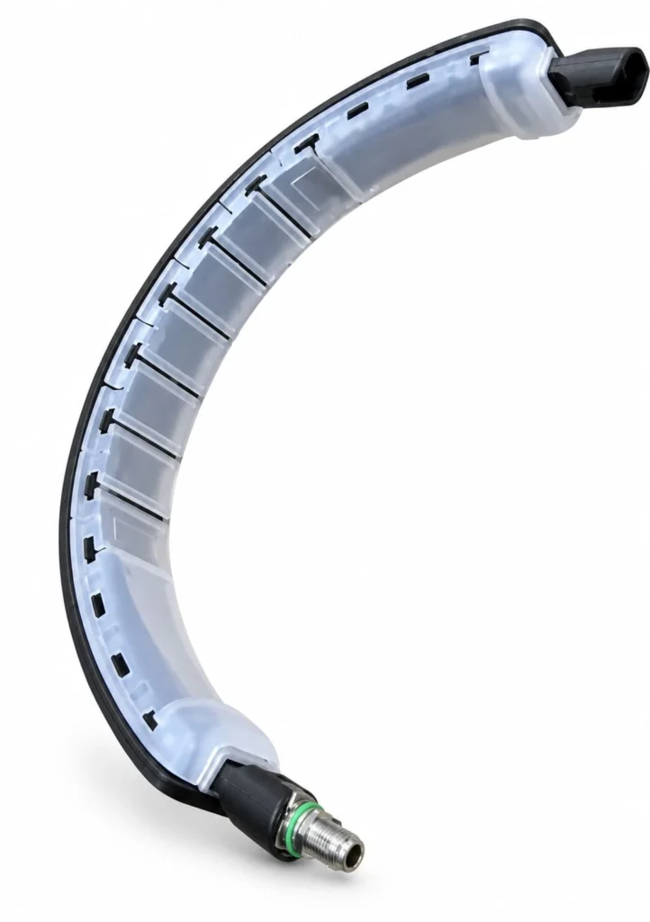
The repeated features along this curved shell make overall shape an assembly issue. End spread or twist can move several engagement points together, even when an individual clip is locally within its dimension limit.
Start with the mating component and its locating sequence. Which feature establishes position first? Which clips retain it? Is the acceptance requirement a free-state profile, an assembled condition, or both? A fixture that forces the part into shape can hide the very variation that makes assembly difficult.
The adjacent assembly view helps explain that relationship. Its translucent appearance does not establish a material grade, hardness or overmolding process.
Measure the relationship,
not just the separate features.
Global shape
Define the arc, end positions and permitted twist in the agreed measurement condition. A single end-to-end dimension cannot describe every form of distortion.
Local engagement
Check clip position, engagement and clearance against the same functional references. Identify which features locate and which accommodate variation.
Assembly behavior
Agree assembly sequence, insertion and retention requirements. Test the complete interface; passing one clip at a time does not demonstrate simultaneous engagement.
Preserve retention.
Question unnecessary tool complexity.
First identify the working snap.
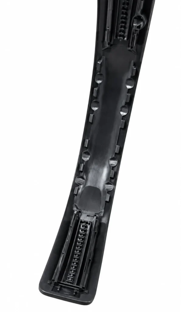
A visible projection is not enough to establish how a clip flexes or releases from the mold. Review root geometry, lead-in, engagement and available deflection space with the mating part. The allowable strain depends on the selected resin and service conditions.
Then compare two routes.
Adjust the feature: changing its orientation or adding tool access may simplify release. Recheck retention, appearance and assembly force before approving that change.
Keep the functional geometry: a side action or another release arrangement may be justified where the interface cannot change. It adds tooling, fitting and maintenance requirements that must be priced into the project.
Do not infer the actual mechanism count from these photographs, or assume that forced demolding is acceptable for an unknown resin and snap geometry.
Compare release options for constrained interfaces ↗Balance the whole interface,
not one isolated snap.
Retention versus installation effort
More engagement is not automatically better. Greater deflection can raise local strain and assembly effort, while too little engagement may release in service. Review the flexible length, root transition, lead-in, engagement face and available clearance together. Use the selected resin’s data and the specified temperature and conditioning; prove the complete assembly behavior on representative parts.
One datum system versus accumulated restraint
If several features all try to locate the mating component rigidly, profile variation can become assembly stress. We would ask which feature must locate and where controlled clearance can absorb variation without losing retention. Any change to that locating strategy belongs to the customer’s assembly design approval, not an undocumented mold adjustment.
A simpler mold versus a changed product
Opening tool access or changing a hook’s orientation may avoid an action but can alter appearance, retention or nearby clearances. Keeping the geometry may justify a side action or another release route, with maintenance and fitting consequences. Neither forced demolding nor a fixed number of slides can be selected from these photographs.
A shorter cycle versus a stable curve
Removing a long thin shell earlier may reduce machine time but can make it more sensitive to ejection and handling. Longer cooling is not a universal cure either. Compare temperature balance, packing history, support and post-mold shape change. Cost should include rejects, rework and assembly losses, not just seconds at the press.
A longer curve connects
many local molding decisions.
Wall and reinforcement
Local thickening at clips or ribs can change cooling, shrinkage and stiffness. Compare a more balanced section with the strength the clip needs; blanket thinning can create a different failure.
Feed and packing
A shorter flow path may help filling but additional gates introduce weld-line and mark locations. Compare layouts against clip roots, the visible outer face and pressure transmission along the arc.
Cooling and release
Review temperature balance and ejection support along the curve. Concentrated force near a still-warm thin section can distort it or damage a clip. Inspect after the agreed stabilization period, not only immediately after ejection.
The outside stays simple.
The inside does the work.
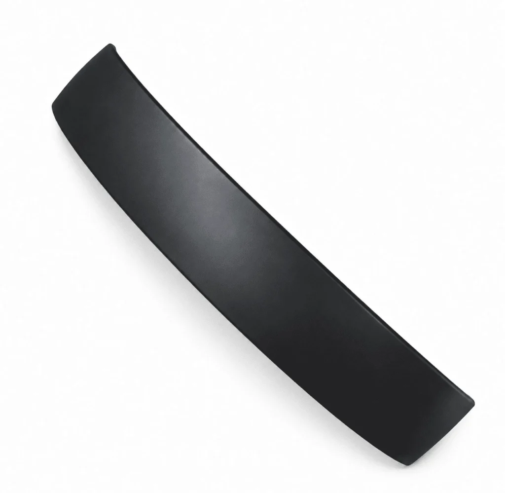
A smooth outer strip can conceal a dense set of assembly features. Clip-root changes should therefore be reviewed from both sides: required retention inside, acceptable sink and surface appearance outside.
For repeat supply, agree a resin grade, appearance reference and revision-controlled acceptance plan. Reducing tool cost by removing necessary support, or reducing part mass without testing the assembly, can move cost into rejects and rework.
Our factory’s direct project responsibility and virgin-material purchasing policy support that discipline. They do not substitute for project-specific dimensional and functional validation.
See how we manage manufacture and quality ↗A trial should tell us
which kind of problem we have.
The local clip is correct; the assembly still misses
Check the free-state profile and relative clip positions before touching the clip cavity. Quality would use the agreed references and compare multiple samples, then repeat the actual assembly sequence. If forcing the part into a gauge makes it pass, the fixture may be concealing the global distortion that causes difficult assembly.
The clip whitens or damages during assembly
Separate damage from mold release from damage caused by engagement. Examine an unassembled molded sample, confirm clearance and alignment, and review the root and mating ramp. Reducing retention by hand polishing without a recorded functional check may create an apparently easier assembly that no longer holds.
The outside sinks opposite an internal feature
Compare the defect with the wall sections, gate location and packing response. Molding would investigate the process within the selected material’s range; design would review local mass and support. A geometry change must preserve clip strength. A cosmetic improvement alone is not evidence of a better functional part.
The curve changes after a waiting period
Record time since molding and the storage or conditioning conditions with each measurement. Check whether the trend follows the setup, cooling balance, resin condition or handling. Do not compare a warm trial part with a stabilized approval sample and attribute the difference solely to mold dimensions.
How CustoMold would take
this geometry into production.
The photographs show a real manufactured reference product. For a new curved, multi-clip component, the following is our proposed project route—not a record of the pictured part’s original tooling or test results.
The project lead would connect the customer’s assembly designer with mold design, fitting, molding and quality. Everyone would work from one approved revision and the same functional acceptance conditions, with the detailed work and testing agreed before commitment.
Agree what the band must do in use.
We would walk through locating, installation, retention and any reopening sequence with the customer. The brief would distinguish structural loading from cosmetic coverage, free-state profile from assembled fit, and fixed interfaces from changeable details. The customer would identify the mating revision and approve the criteria for force, gaps and service testing.
Decision record: An interface map, measurement condition and agreed functional test brief.
Make the alternatives reviewable.
The mold designer would section every relevant clip and propose the release route. The customer would review any product changes; the molding lead would assess fill length, root sections, feed positions and support during cooling and ejection. The toolroom would check whether fine shutoffs and narrow forming features can be made, fitted and maintained.
Decision record: A comparison of geometry-change and tooling-action options, including cost and functional risks, followed by an approved DFM.
Protect small features and the global relationship.
Before trial, the fitter would inspect shutoffs and any moving cores for contact, clearance and return, and check ejector travel and support. Forming features affecting retention would be identified so polishing or repair cannot casually change engagement. The designer and quality lead would tie inspection references to the approved assembly, not just convenient tool edges.
Decision record: A checked mold, critical-feature references and a fitting record linked to the current drawing.
Learn from tagged samples, not selected good parts.
We would record the resin, its preparation, mold condition and trial setup. Filling, packing, cooling and release would be assessed in a controlled sequence. Quality would track profile, twist, end positions, clip locations and appearance after the specified stabilization. If adjustment is needed, the fitter and molding lead would agree whether the evidence points to the tool, process or geometry.
Decision record: A sample-linked issue log with a reason for each adjustment and the characteristic that must be rechecked.
Prove the full engagement sequence.
Trial parts would be assembled with the intended mating components in the agreed order. We would check insertion and retention behavior, closing gaps and local whitening or damage, then conduct the specified reopening or service-condition tests. A clip that works in isolation would not close an issue that appears only when the whole curved assembly is installed.
Decision record: A dimensional and functional approval package with representative samples, test conditions and remaining deviations.
Preserve the approved fit through the next batch.
The production handoff would define material and revision identification, approved setup limits, first-off and in-process checks, mold maintenance and handling. Packing would avoid imposing an uncontrolled bend during storage. Any clip repair, resin change or process shift affecting the curve would be assessed against the original acceptance conditions.
Decision record: A control plan, appearance and assembly references, packing instruction and reapproval triggers.
From a molded arc
to an accepted assembly.
Set the condition
Define free-state or assembled checks, datums and time after molding. Include service conditioning where relevant to the resin.
Record the part revision, material and measurement setup so the next batch is evaluated on the same basis.
Check the fit
Inspect overall profile and clip positions, then assemble with the intended mating component in the specified sequence.
Measure agreed insertion/retention behavior and inspect for whitening, damage or an uneven closing gap.
Qualify repetition
Use the required assembly cycles and service conditions where repeat opening is part of the product requirement.
Assess representative trial-run samples and the approved process window. One assembled sample is not evidence of stable production.
This is a proposed verification framework. No cycle-life result, yield, tolerance capability or resin identification is claimed for the photographed headband.
Use the same reasoning
at a different scale.
In a large ribbed projector housing, the mounting datums and closing rim depend on overall shape. The geometry differs, but checking local details without the assembled condition creates the same blind spot.
Read the large-housing engineering review ↗Our precision cartridge case is a separate, implemented manufacturing project. Its chip interface connects position, spacing and height requirements to real tooling decisions and continuing part production.
See the implemented cartridge tooling ↗Show us the curve.
And everything it has to engage.
Send the part and mating CAD, material specification, cosmetic faces, expected volumes and the features allowed to change. Identify the locating sequence, target assembly behavior and whether the part must be opened repeatedly.
We use those inputs to assess tooling and injection molded part supply, with agreed design changes and a practical sample-approval plan.
Technical reference: Covestro, Snap-Fit Joints for Plastics, for material-dependent strain and engagement considerations. Use the selected grade’s current data; this does not identify the resin or approved snap geometry of the pictured part.