A small gate vestige.
A larger assembly question.
A trimmed gate is only acceptable when the part still fits and works. Review the residual envelope, the neighboring component and the checks needed for repeat production.
The relevant surface
belongs to two parts.
A trimmed gate area can matter when another component sits, locates or passes close to it. Reviewing the molded part alone does not show that relationship.
Identify the gate position and the finishing condition, then compare them with the actual mating geometry and the function of the contact area. Without that information, a clearance number is only an assumption.
The gate decision reaches
the button’s working envelope.
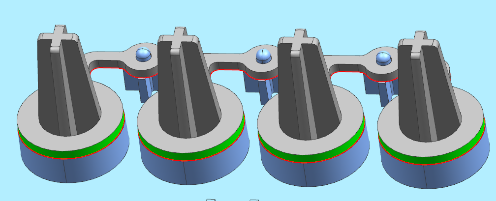
The small-parts review proposes adding 0.3 mm at the green face of a button to avoid interference around the gate area. This is a local geometry proposal. It is not a specification that a 0.3 mm gate vestige is acceptable.
A separate decorative-cover review proposes a lap gate and a recess in the mating component. Both examples show why the finished gate area must be reviewed inside the assembled product.
What we need to resolve
Identify which face sets button height or travel, what locates the button and what clearance remains through its movement. If another component needs relief, confirm that its locating or support function can tolerate the change.
The decision should describe the accepted geometry and trimmed condition together. A static CAD gap alone cannot define the supplied part.
Pre-tooling reference: small-parts DFM, sheet 3; decorative-cover DFM, sheet 3. Engineering review by CustoMold.
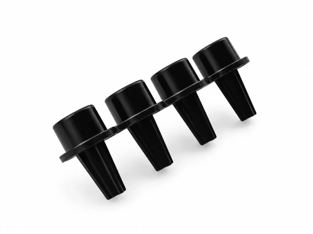
The reverse side explains why clearance matters.
The molded four-button carrier shows the stems and locating features that sit behind the visible controls. Their position relative to the cover and electronics determines where movement is needed—and where a finished gate must not interfere.
Review the local gate proposal ↗Three options.
More than one constraint.
The right discussion connects tool design, part finishing and the assembly. Solving one local issue should not silently create another.
| Option | Potential purpose | Checks before choosing | Approval required |
|---|---|---|---|
| Review gate location | Place the gate area away from a sensitive interface. | Filling, weld-line position, appearance and tool arrangement. | Manufacturing proposal and permitted gate marks. |
| Add local mating-part relief | Provide space around the finished gate area. | Contact function, strength, location and nearby geometry. | The owner of the affected mating component. |
| Define trimming and gate-area acceptance | Control the part condition supplied to assembly. | Practical finishing method, inspection reference and repeatability. | The accepted finished condition and inspection method. |
These routes may be combined. A gate-location discussion does not remove the need to define the finished part, and a drawing relief does not establish that every future assembly will fit.
Control the trimmed edge
and the assembled fit.
The lower-cover review specifies a 5 × 1.2 mm gate with manual removal. The backplate review specifies a 3 × 1.0 mm gate with manual trimming. These gate dimensions describe the proposed tooling; neither defines the permitted residual material on the finished part.
Define the envelope
Mark where residual material may remain and where it would obstruct a mating part. Agree the relevant drawing reference and limit.
Agree the trim method
Evaluate access, damage risk and the finish the operation can repeat. Check for both excess material and removal into the required surface.
Check the assembly
Review samples after the intended trimming operation with the current mating components. Include travel or closing fit where relevant.
Carry the reference forward
Include the accepted gate condition in the production inspection plan. Revisit it after changes to the gate, trimming process or mating geometry.
Source: lower-cover DFM, sheet 3; backplate DFM, sheet 3. The inspection approach above is a proposed project requirement; no repeatability result is supplied.
Include what sits
next to the gate.
Provide the part and relevant mating CAD, current revisions, the proposed gate area and the function of the nearby surface. Mark any changes that are not permitted.
Why no universal residual-height limit?
The useful limit depends on the part, the finishing method, the mating geometry and the acceptance requirements. A dimension from one supplier example is not a general rule for another product.
Further reading: Autodesk: weld-line troubleshooting and gate-position trade-offs.

A local surface can control
the complete product.
A gate remnant can interfere with a mating component. In a different kind of interface, our cartridge project shows why narrow outlets and a chip-bonding face must also be judged together.
The cartridge case concerns passage separation and alignment, rather than a gate-vestige correction. Both examples show why the adjacent component and the acceptance criteria belong in the manufacturing discussion.
Explore the cartridge interfaceGate clearance and panel support answer different questions.
A trimmed gate needs space. A locating rib may need contact. In our enclosure case, peripheral ribs were recommended to support and locate a flat panel with four screws. Define where contact is intended before applying a general clearance rule to the whole assembly.
The case concerns sliders and support geometry; it does not establish a gate-vestige limit for your part.
See the panel-support decision ↗Review the gate area
in its assembly.
Bring the molded part and its neighbor into the same manufacturing discussion.