Large projector housing.
Stiffness is only one requirement.
A large ribbed enclosure needs more than stiffness. Review how rib junctions, mounting datums, mold cooling and any specified conductive coating affect the finished assembly.
A real manufactured reference product. This review explains the engineering decisions and how CustoMold would approach a similar project. For work already implemented by CustoMold, explore our manufacturing cases.

Before quoting the tool,
define what must stay in place.
What carries the load?
We would ask for the complete mating assembly, not just the outer shell: mounting brackets, optical-module supports, cover, fasteners and any inserts. Which faces establish the functional datum? Which loads are carried by the plastic, and which by a separate frame? A boss that only retains a cover needs a different review from one that locates an optical assembly.
What can change—and what cannot?
Mark the lens opening, connector positions, ventilation area, visible faces and fixing points that are frozen. Identify where rib placement, boss support, wall transitions or access for molding may change. We would return a marked-up change list for approval rather than quietly simplifying the CAD to suit the mold.
What happens after molding?
Confirm whether the shell is used as molded, painted, coated for conductivity or combined with shielding hardware. Ask for the actual coating specification, contact and masking map, cure conditions and final inspection state. This determines whether a dimension is accepted before finishing, after finishing or in the completed assembly.
What does the order require?
Obtain the resin grade and allowed alternatives, expected lot sizes, annual demand, appearance reference and delivery format. Confirm tooling ownership, maintenance expectations and any service-life requirement. Machine size and a delivery date would be confirmed against a reviewed manufacturing route, not estimated from a product photograph.
A rib network has to preserve
the surfaces that locate the assembly.
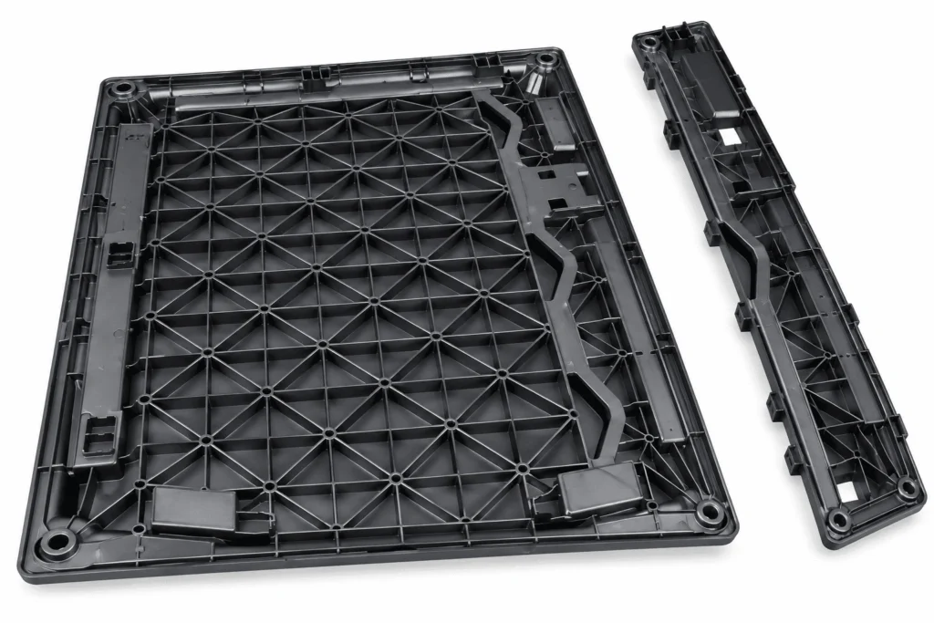
The interior image shows intersecting ribs, mounting bosses and reinforced edges. These features invite a more useful question than “is the shell rigid enough?”: which surfaces must stay in position when the internal assembly is fastened?
Identify the mating rim, mounting faces and fastener locations in the CAD. A shell can feel stiff yet still rock on its mounting points or close with an uneven gap. Those functions should define the datums and the dimensions to check.
Adding ribs may improve support, but closely spaced intersections can concentrate material and complicate filling, cooling and release. Assess rib roots and boss connections against the visible outside face before making them thicker.
Follow the consequence
to the other side of the wall.
Support where the load enters.
A taller or better-placed rib may provide support without thickening the entire panel. The trade-off is deeper tool geometry and greater release resistance. Confirm the actual load path before adding a dense grid everywhere.
Reduce mass at a junction.
Relieving a crowded rib or boss connection may reduce local heat concentration. It can also reduce stiffness or change fastening support. Compare sections in CAD and preserve the approved interface.
Keep the show face in view.
An internal reinforcement can influence sink or gloss on the outside. Review both faces together, using an agreed appearance reference and inspection lighting rather than accepting a hidden feature in isolation.
Price the decisions.
Do not hide them inside a mold quote.
Ribs and bosses: stiffness versus local mass
We would map ribs to load paths and mounting datums, then inspect their roots and intersections in CAD sections. Possible changes include coring a boss, relieving a congested junction or redistributing support. A thinner root may reduce local mass but cannot be approved without checking load transfer, fastening and the visible face. No single rib-to-wall ratio is a substitute for the selected resin and functional requirements.
Side features: tool access versus product freedom
For each grille or side opening, compare a parting-line or shutoff solution with a moving core. The first may need a product change or place a witness line on a visible face; the second adds travel, support, wear surfaces and maintenance access. A mold fitter must be able to establish and maintain the shutoff. The agreed cosmetic boundary belongs on the drawing.
Gating: pressure transmission versus new flow joins
Compare gate positions against flow length, thin sections, venting opportunities, appearance and load-bearing regions. Multiple feeds may improve access to distant areas while creating additional flow joins and a more complex runner system. Where justified, flow analysis would screen alternatives; trial filling and measured parts would still be needed to validate the chosen route.
Equipment: confirm the complete fit
Review projected area and estimated cavity pressure together with shot volume, plasticizing capacity, pressure and speed capability. Then check tie-bar spacing, platen support, mold mass, opening and ejection travel, lifting and handling. A larger clamping-force rating alone cannot correct poor venting, inaccessible cooling or a mold that the production equipment cannot handle.
Choose the manufacturing system.
Not just a machine tonnage.
Match the mold and the machine.
Size alone does not establish a press requirement. Review projected area and estimated cavity pressure for clamping, then shot capacity, injection performance, tie-bar clearance, opening stroke and mold weight. Machine selection follows the actual part and mold design.
For a large housing project, that equipment fit is an early feasibility check. The product photographs do not establish a particular press size or our available machine capacity for your design.
Compare gate, cooling and release choices.
More feed points may shorten flow paths but introduce additional weld-line locations and balancing requirements. Put those locations against visible faces and loaded interfaces before selecting a layout.
Cooling access around deep ribs and bosses, together with distributed ejection support, deserves the same attention. Review each side opening against the chosen pull direction; a photograph cannot determine whether a slide or a shut-off is the right solution.
Review side openings and mold release ↗If conductive coating is specified,
design for the next process too.
Conductive coating is a possible functional requirement for an electronics enclosure. The supplied photographs do not prove a coating specification or shielding performance. If your design calls for it, bring the coating zones, electrical contacts and insulation boundaries into the tooling review.
A rib that helps the structure can obstruct access to a deep pocket during spraying. A coating that covers a fit surface can change clearance. A cure cycle may also change the molded shape. Qualify the selected resin and coating system together, then check the finished assembly after the complete process.
Define the conductive path.
Identify required coverage, contact points and seams with the product’s electrical designer. Do not assume every internal face must be coated.
Protect the other functions.
Specify masking for insulation, bonding and dimension-sensitive areas. Check access to rib sidewalls and deep pockets before fixing the process route.
Separate the acceptance levels.
Coating coverage, adhesion and specified electrical measurements address the coating process. They do not replace the completed product’s applicable EMC testing.
A good molded shell can still fail
at the next operation.
For a coated version, the manufacturing review must follow the part through cleaning, masking, spraying, cure, handling and assembly. We would ask the finishing team to assess the same CAD revision before releasing steel. Otherwise a rib added to solve stiffness may create an inaccessible pocket, or a contact redesigned for molding may no longer match the electrical plan.
Make the coverage map inspectable
Identify required conductive zones, intentional insulation and electrical contact points. Deep cells between ribs need accessible spray angles and inspection points; coating only the most visible surfaces does not demonstrate continuity. Where access is poor, compare local rib relief, a different application approach or a revised shielding interface with the customer’s designers.
Qualify a material–coating combination
Check substrate compatibility, surface preparation and the specified coating cure on representative parts. A mold-release aid that helps ejection may interfere with coating; a resin change that helps filling may need renewed finishing validation. Cleaning and coating instructions therefore belong in the process route, with material substitutions subject to approval.
Inspect after the full thermal history
Record critical dimensions before and after the approved finishing cycle under agreed measurement conditions. If a rim moves during cure, investigate part stress, support and cure conditions together. A fixture used for transport or cure must not merely force a distorted shell into a temporary passing shape.
Keep component and system approval separate
Agree coverage, adhesion, dry-film requirements and electrical test points using the selected coating specification. The customer’s electrical team must also define contacts, seams and openings for the complete shielding system. Passing a coating resistance check cannot establish the assembled product’s EMC compliance.
How CustoMold would run
a housing project like this.
This is our proposed delivery plan for a new project with comparable features. The illustrated housing is a real manufactured reference product; the steps below describe how we would develop your project, not how this particular part was produced.
One project lead would maintain the approved revision, open decisions and acceptance requirements across the customer, mold designer, toolroom, molding, finishing and quality teams. Responsibilities, equipment availability and any required testing would be confirmed in the project scope.
Turn a product brief into a shared risk map.
We would review the assembled CAD with the customer and identify the lens opening, mounting references, cover gap, appearance zones and any shielding interface. Each issue would state the consequence, the proposed change and who can approve it. Where a requirement is missing, we would identify the decision it blocks rather than silently choose a tolerance.
Decision record: A marked-up DFM, a critical-feature list and a customer-approved change register before steel release.
Compare feasible routes with their consequences.
The mold designer and molding lead would compare parting, side actions, gating, cooling and ejection as a connected layout. The toolroom would review machining and fitting access; the finishing team would review coating access where required. The quote would distinguish essential tooling from options and identify unconfirmed material, test or equipment assumptions.
Decision record: An approved mold concept, manufacturing route and scope with explicit assumptions and acceptance gates.
Fit the mold against the intended function.
The mold fitter would check parting and shutoff contact, moving-core clearance and return, ejection freedom and the support behind critical forming areas. Cooling circuits would be identified and checked for leakage and usable flow. The designer would review any fitting adjustment that changes a functional surface, so hand correction does not drift away from the approved model.
Decision record: A build and fitting checklist, revised drawings where needed, and an open-issue list for the first trial.
Separate fill, release and dimensional problems.
Using the selected resin’s processing guidance, the molding lead would record material preparation and the actual setup. A controlled trial would examine filling and venting before evaluating packing, cooling and ejection. Quality would measure identified samples after the agreed stabilization condition. The fitter would inspect flash, drag and local damage with the process engineer before anyone removes more steel.
Decision record: A traceable trial report: sample IDs, setup, dimensional and visual findings, proposed actions and the next verification.
Release the finished condition.
Where coating is specified, representative trial parts would pass through the intended cleaning, masking, application and cure route. We would compare mounting and closing dimensions before and after finishing, check the specified coating properties, then assemble with the intended hardware. The customer would coordinate the complete product’s required EMC approval.
Decision record: A finished-part inspection report and approved reference samples; unresolved assembly or coating issues remain open.
Control the route that produced the approval.
Before repeat supply, we would agree the resin, mold revision, setup limits, inspection frequency, material and lot identification, handling and packing method. A representative production run would test whether the approved result is repeatable. Maintenance would focus on shutoffs, vents, moving parts and cooling; a material, tool or finish change would trigger the relevant revalidation.
Decision record: A released control plan, approved sample reference, setup record and change-control requirements.
Approve the condition
the customer actually receives.
Molded geometry
Review: rim profile, mounting positions, rib fill and outside appearance.
Verify: defined datums, conditioning time and inspection method; trial assembly with the actual mating parts.
After any coating
Review: required coverage, masking, adhesion and electrical contact requirements.
Verify: the coating specification, then recheck critical fit after cleaning, application and cure.
Repeat production
Review: material grade, fill/pack/cool settings, sampling and mold condition.
Verify: agreed critical features across a representative trial run; record deviations and their disposition before release.
These are proposed validation gates, not reported test results for the pictured product. Agree the limits and responsibility for each check before tooling.
Bring the housing.
Bring what goes inside it.
For a tooling and production quote, share the housing and mating CAD, overall envelope, intended resin, order quantities, visible faces and critical mounting datums. Include the complete coating and electrical-contact specification if it applies.
CustoMold connects the approved design review with mold development, sample approval and part supply. Equipment fit, any specialist finishing route and the acceptance responsibilities belong in the agreed project scope.
Technical reference: MG Chemicals, ER shielding-coating application guide (product-specific preparation, masking and cure guidance). Use the selected coating’s current specification; this reference does not identify the coating on the pictured product.