The outside protects.
The inside performs.
Injection molded housings, covers and mating parts for products where side openings, internal geometry and visible surfaces have to work together. Built from your design and its assembly requirements.
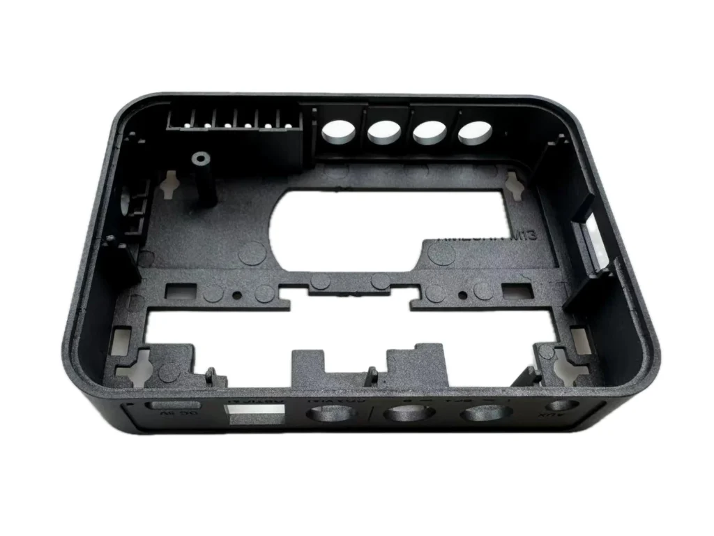
A clean exterior.
A panel supported from within.
The customer’s zero-draft requirement led to four side sliders. The finished exterior showed no visible slider junction lines. Inside, we recommended peripheral ribs to support and locate the flat mating panel together with its four screws.


The engineering value is in the relationship.
The outside shape constrains tool release. The inside ribs affect support, location and deformation. Screw positions influence how the panel closes. We review those as one assembly, so a moldability change does not quietly compromise the product.
See the complete enclosure case ↗Recognize the assembly
inside the shell.
Our molded examples include removable interface panels, button guides and covers that meet along a visible perimeter. Their shapes differ, but the starting point is the same: what must locate, move, close or remain accessible?

Guides, bosses and board location
Review the internal features with the electronics and screws. A stronger-looking boss is not automatically the right boss.

Openings across several faces
The hole pattern, control positions and side interfaces create connected tooling and appearance decisions.

The cover changes the clearance
Judge port access and the visible seam with both components assembled.
It is a housing.
And a fluid interface.
The cartridge shell encloses three ink paths and positions three narrow outlets against a bonded chip. Internal partitions, the outlet pattern and the bonding surface all contribute to the finished function.
Our mold redesign combined internal and external slides with angled core-side withdrawal in one mold. The project is in ongoing injection production.
If your enclosure locates a seal, connector or bonded component, we start with the same question: which surfaces and datums must remain related after molding?
See the complete cartridge case
The connector opening
sets more than its diameter.
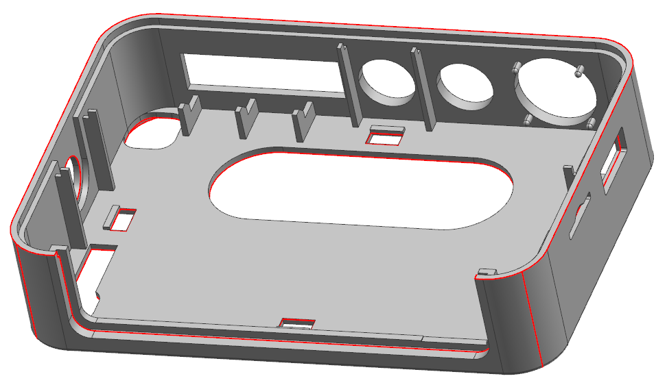
A close fit for this service: a housing with fixed connector positions, several side openings, a visible outer wall and internal locating features.
The reviewed upper cover has four proposed side actions. The report separately addresses draft along the slide direction; another housing review links thick internal ribs to a risk of sink on the sidewall.
Our judgement: the opening location, its mating connector and the acceptable split line have to be held together. Simply adding draft or deleting a slide can change the useful opening or the way the connector is supported.
Mark the interface that must remain fixed. Then compare the tool-release direction, the section at the functional opening and the visible boundary. A local change is useful only if it preserves the fit the customer needs.
See two source reviews and the decision sequence ↗Pre-tooling reference: upper-cover review, sheets 1–4 and 8–11; second upper-cover review, sheets 7–12. Engineering review by CustoMold.
Three more product patterns.
Three different engineering decisions.
The examples below use pre-tooling review material to show our reasoning. They are useful if your design has the same combination of visible surfaces, mating parts and manufacturing constraints.
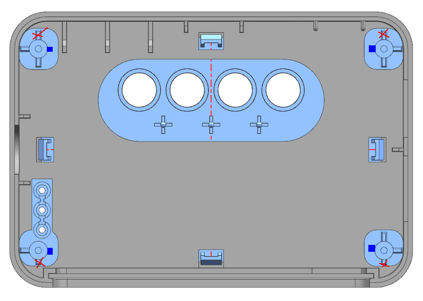
A cover rib can occupy the space another part needs.
Product match: an equipment cover with bosses, clips and a close-fitting lower shell.
Source detail: sheet 6 proposes removing 0.2 mm locally at four ribs near the lower cover. Sheet 10 proposes moving corner ribs so the lower cover can accommodate ejectors. These are two different changes, not one universal clearance rule.
Our judgement: identify what each rib locates or supports before changing it. Review the two part revisions together. The toolmaker confirms the ejector arrangement; the customer confirms the allowed change to fit and support.
Sample check: inspect the relevant corner surfaces after ejection, then close the housing with the intended components. Do not replace that check with approval of a single isolated part.
Read the cross-part decision ↗More clearance can help movement and hurt light shielding.
Product match: a control face with molded buttons or an indicator component passing through a cover.
Source detail: one product review identifies a gap issue at a mating section and separately proposes adding material to button skirts for a light-leakage concern. A light-guide review also ties draft changes to its upper-cover fit.
Our judgement: there is no single “make the gap bigger” correction for the whole assembly. Track movement clearance, overlap for light shielding and the locating shoulder as different requirements. A change that helps one can consume another.
Sample check: use the actual cover, board, switch and light source where relevant. Check the agreed button movement and unwanted visible light; optical or life-test requirements need their own defined test scope.
Pre-tooling reference: product-analysis sheets 2–3; light-guide sheet 3. Engineering review by CustoMold.

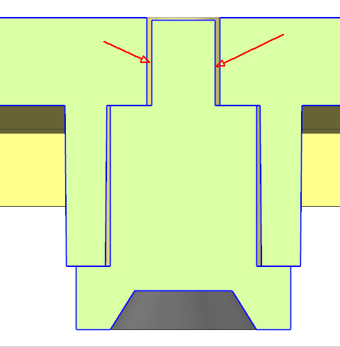
Keep the common outline.
Choose what the tool may share.
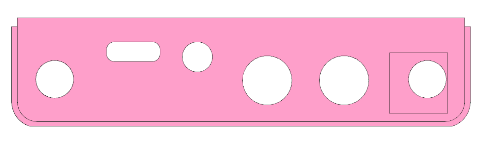
Product match: a family of equipment using related backplates with different connection layouts.
Source detail: the report compares additional cavity/core components with a common cavity that requires accepting a slight local shutoff mark.
Our judgement: the right scope depends on where the mark appears, which mating dimensions cannot change and the quantities for each version. A lower initial tooling figure can leave appearance or changeover requirements unresolved.
Production check: distinguish the versions at setup and in inspection/packing. Record which tool components and reference part belong to each version.
Compare the two tooling scopes ↗Hole geometry and surface acceptance
need separate decisions.

A grille-like cover is another relevant part when the hole pattern and surface both matter. The supplied report asks the customer to confirm the hole shape, proposes changes at the hole shutoff and discusses limit samples for visible marks.
Our judgement: confirm the opening that the product actually requires before optimizing the shutoff. Then agree appearance independently: a geometrically acceptable hole does not automatically establish an acceptable visible surface.
The production scope can therefore include two different references: the released hole geometry and the agreed finish/appearance sample.
Follow the shutoff example ↗ Define appearance acceptance ↗Pre-tooling reference: perforated-cover review, sheets 9–10 and 14–15. Engineering review by CustoMold.
Bring the features that
cannot be changed.
A useful starting point
- An existing enclosure, cover or panel design and the relevant mating components.
- Visible surfaces, fixed connector locations, locating features and fastener definitions identified.
- A tooling and molded-part requirement, with first-order and repeat-order quantities stated or open for discussion.
Where the scope needs a separate check
Optical performance, sealing ratings, electrical approvals, demanding cosmetic finishes or structural-life requirements cannot be inferred from similar-looking geometry. Name the required result so the manufacturing and validation scope can be assessed.
You can start with incomplete inputs. We identify which missing item prevents a particular decision instead of treating every unknown as a reason to stop.

Review the enclosure
as an assembled product.
- Check the visible faces against the agreed reference.
- Fit the lid and the parts that locate inside it.
- Check screws, access openings and connector interfaces.
- Record what is accepted and what needs a revision.
Any sealing, optical, flame or other performance requirement needs its own agreed specification and verification.
When the housing becomes
a structural assembly.
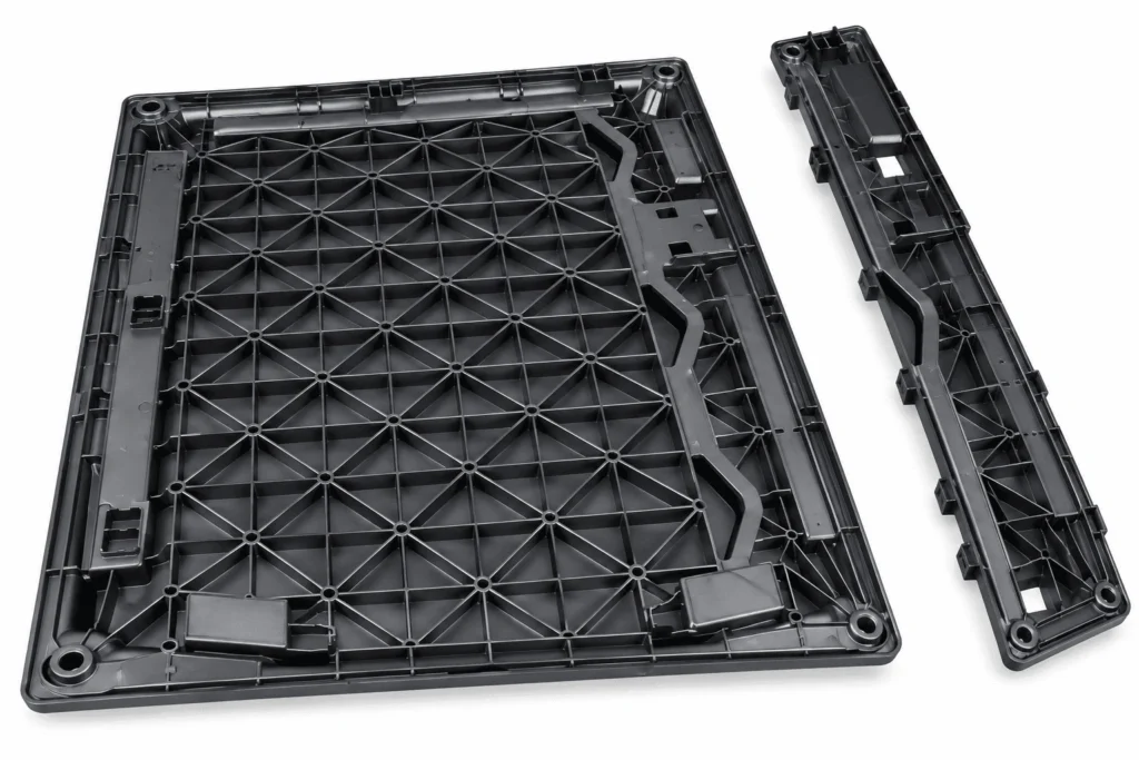
A dense triangular rib network and several mounting bosses make stiffness, shrinkage and datum control interdependent. Adding support can also change the visible face or access for a specified coating.
Our large-projector housing review follows those trade-offs into molding and finished-assembly checks. It is a geometry-based engineering interpretation, separate from our implemented enclosure case.
Read the ribbed-housing review ↗Show us the shell.
And the parts it must fit.
Send the enclosure pair, relevant mating CAD and the features you cannot change.
Your shell can do more
than hold the assembly.
A soft contact region can change how a housing is handled. A molded texture can change how its show surface reads. Both need to be planned around the ports, parting lines and mating features.

A surface finish that belongs in the tool.
Our bright-pattern housing uses specialist laser processing of the mold. A restrained visual feature can still require a careful tooling investment and a defined appearance reference.
See the molded surface finishA different feel where the product needs it.
If your enclosure needs a softer grip or contact zone, identify its function and boundary before tooling. Material pairing and retention need to be reviewed with the complete shell.
Review soft overmolding