Zero draft.
Four sliders.
One complete assembly.
An implemented CustoMold enclosure project, shown through its molded parts and the decisions used in the tool. The zero-draft requirement, four side slides and assembly-support recommendation belong to this actual project.
A customer-required zero-draft exterior called for four side sliders. The same enclosure also needed to support a flat mating panel. See how tooling, visible finish and assembly reinforcement were considered together.
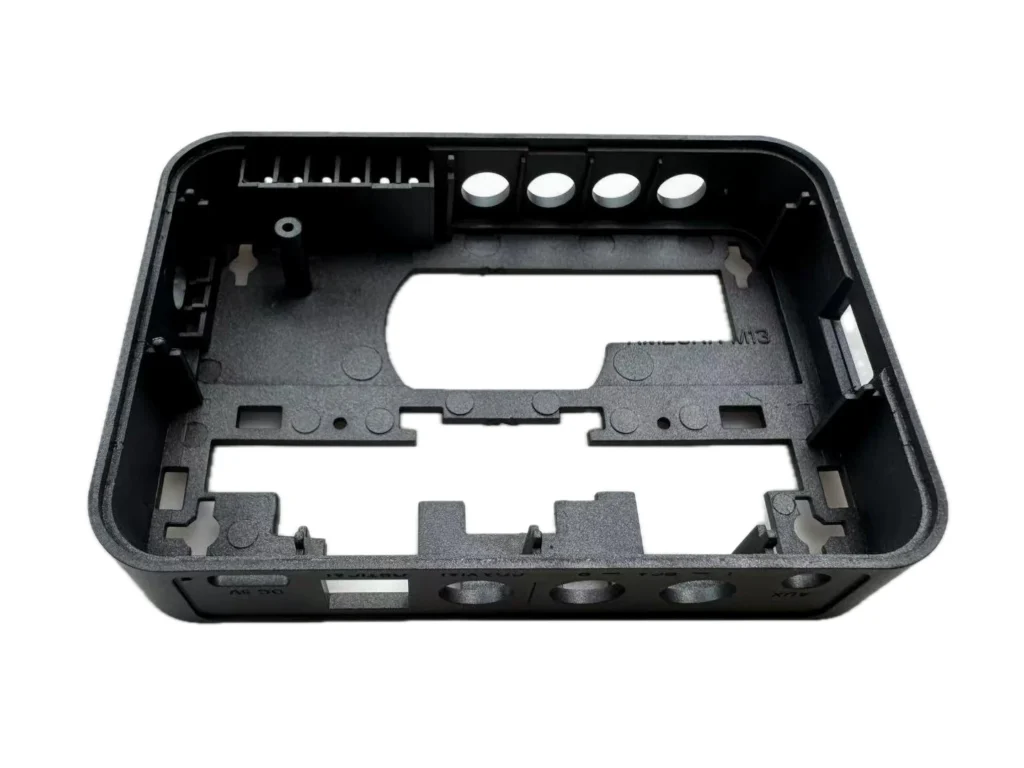
Change how the tool opens.
Keep the required wall geometry.
The customer required zero draft on the enclosure’s specified walls. We designed four lateral sliders around the part, bringing the release arrangement into the tooling concept rather than simply changing the customer’s exterior shape.
That choice carries a second responsibility: four moving elements must return to the correct position and meet consistently. The release direction, the steel interfaces and the visible surfaces have to be considered together.
Zero draft describes the specified faces in this project. Each opening, rib and shutoff still needs to be reviewed relative to the direction in which its forming steel withdraws.
How we review side openings and slides ↗
Four sliders.
No conspicuous seams on the finished exterior.
The finished parts achieved the project’s appearance outcome: no visible slider junction lines on the intended exterior surfaces. The photographs show the physical molded enclosure and its surface finish.
That result connects the mold design to tool manufacture, fitting and molding. It is more useful than showing a release concept alone: the part still has to look right after it comes out of the tool.
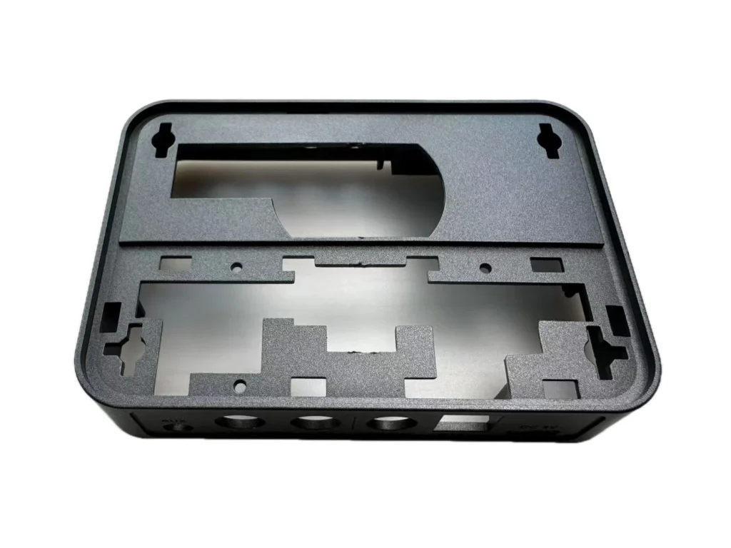
A mold still has physical interfaces between steel components. For a new project, define the visible faces, viewing conditions and an agreed appearance reference; do not substitute a blanket “seamless” promise for those requirements.
The screws secure it.
The ribs help support and locate it.
This enclosure mates with a flat panel. We recommended peripheral reinforcing ribs to the customer’s designer so the part would have support and location around its edge, alongside the four screw positions. The aim was to resist deformation and support the assembled product.


One change. Three connected jobs.
- Support the panel.Give the mating plane support around the perimeter, instead of relying on four isolated fastening points.
- Locate the assembly.Use the peripheral features to help establish the panel’s position as the housing closes.
- Resist distortion.Review the rib support with screw tightening and the assembled condition. More rib material is not automatically better: local wall thickness and the visible exterior still matter.
The recommendation addressed assembly behavior as well as moldability. For another design, rib height, contact, clearance and fastening requirements must be agreed against the actual mating part.
Inspect the complete interior and perimeter ribs

Keep the appearance.
Keep the assembled fit.
This case demonstrates the implemented tooling approach, molded appearance and assembly-driven design recommendation. For repeated supply of a comparable part, the acceptance discussion needs to preserve all three—not only the outside dimensions.
Visible boundaries
Identify the slider junction regions, texture and viewing conditions. Agree which reference represents acceptable appearance.
Assembly support
Check the intended panel, locating features, four fastener positions and the assembled condition under the agreed fastening method.
Tool and revision
Keep the accepted part revision, material and tool condition connected to repeat orders. Revisit fit and appearance when those inputs change.
For your project, we agree the checks and sampling scope around its functional risks. This case does not supply a measured seam-height limit, flatness result or process-capability statistic.
Explore tooling and molded-part supply ↗Similar geometry.
A separate DFM review.
The related upper-cover review also uses four side actions and considers side openings, parting locations and direction-specific draft. It is a useful comparison for understanding the questions a toolmaker asks.
It belongs to a different, similarly structured product. Its local draft proposals are not the specification for this zero-draft enclosure, and the drawing is not presented as this case’s production mold.
Read the direction-specific review ↗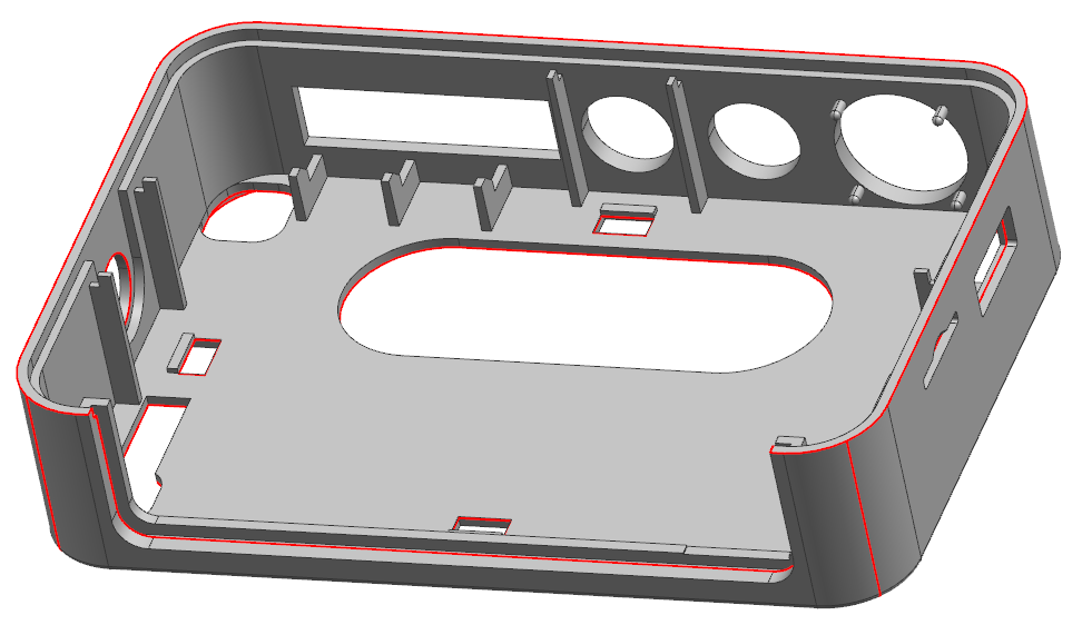
A fixed exterior. Several side ports.
A cover that has to fit.
Your product may look different and still need the same kind of engineering judgement. Send the enclosure pair, identify the surfaces that cannot take draft, and show how the cover is located and fastened.
Bring the shape you need.
Show us how it has to assemble.
We will review the tooling and molded-part supply scope together.