Build the mold.
Keep the part in production.
Custom mold development and injection molded part supply, from functional housings to demanding precision interfaces. Connect engineering review, tool manufacture, sample approval and repeat production.
Your design · Custom tooling · Sample review · Production parts

One manufacturing route.
Five clear handovers.
Tooling decisions affect the parts you buy. We connect the design revision, mold scope, sample approval and production requirements so that each handover has a clear technical basis.
Define the part's job.
Share the current CAD and drawing, the mating parts, fixed interfaces and quantity outlook. Identify where appearance, sealing, movement or alignment controls acceptance.
Agree the tooling route.
Review gates, parting lines, shutoffs, side actions and ejection against the product requirements. Record the geometry changes to approve and the functions they must preserve.
Build and fit the mold.
Connect machining, EDM, grinding and fitting to the agreed tool design. Moving inserts need a release path, guidance and a reliable working position—not just clearance on a CAD screen.
Review the molded parts.
Check the actual part against critical dimensions, appearance references and mating components. Keep corrective actions and the production-release decision tied to the same revision.
Supply and repeat.
Confirm the approved material, part revision, quantities, packing and acceptance references. Review changes to the tool, process or mating components before treating the next order as identical.
The detail has to work
in a moving mold.
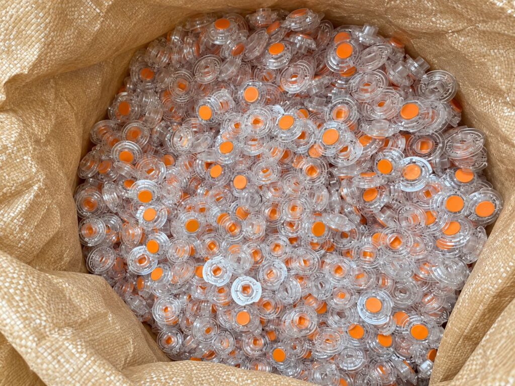
Our cartridge mold combines internal and external slides with angled core-side withdrawal. The toolroom work connects these movements to supporting steel, precise contact and the molded geometry they produce.


Two molds became one.
The part stayed central.
The cartridge project brought three separate ink outlets and a bonded chip interface into a single production mold. Internal and external slides and angled core-side withdrawal enabled the required geometry to release.
The project reached the intended part result and continues in production. Its value comes from combining functional precision with a workable manufacturing route.
Explore the part, mold and production evidenceTwo versions do not automatically
mean two complete molds.
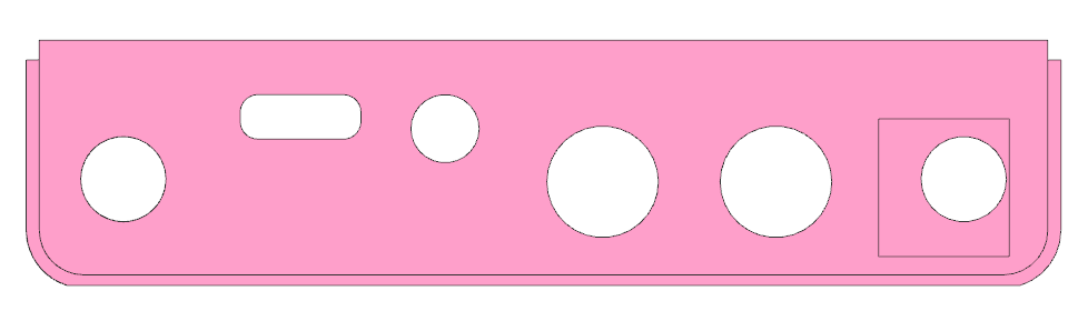
A backplate review presents two approaches for replacement versions. This is a procurement decision as well as a tooling decision: the interfaces, acceptable marks and order mix determine what is worth comparing.

| Route in the report | What changes | What we need to decide |
|---|---|---|
| Two cavity blocks plus two replaceable core inserts | More version-specific tooling components are identified. | Which dimensions remain common? How are the correct components matched to each version? What are the setup and verification requirements? |
| One cavity block, accepting slight local marks at the shutoff hole | The report makes appearance acceptance part of the shared-tooling option. | Where is the affected opening in the assembled product? Can the customer accept the proposed mark? Does the opening still meet fit and edge requirements? |
Our judgement: decide whether the mark is acceptable before treating the common-cavity route as a saving. If the feature is visible or its mating interface cannot change, the extra tooling may be the better scope. Compare quotes using the same material, finish, quantities per version and acceptance requirements.
For your project, the quotation should separate initial tooling, version-specific components, changeover work, sample approval and part prices. Tool ownership, maintenance, storage and transfer terms are agreed in the commercial scope.
Pre-tooling reference: backplate review, sheet 7. Engineering review by CustoMold.
Repeatable supply needs
a repeatable acceptance reference.

Perforated-cover review, sheets 2 and 9–10.
Appearance: define the boundary before the order.
The supplied review flags visible weld-line and stress-mark concerns and proposes signed limit samples for production. It also discusses painting when the requested appearance cannot be accepted as molded.
Our judgement: the finish route belongs in the part specification and price. Confirm the visible zones, color/texture reference and viewing conditions. If painting is considered, its coverage, fit impact and acceptance need separate confirmation; it is not an automatic cure.
A sample that everyone calls “good” is a weak reference unless the approved revision and acceptance conditions are identifiable.
Carry each engineering issue into the production plan
The table below is a proposed control-plan outline for these example features. The actual measurement method, sampling frequency and acceptance limits must be agreed for the project.
| Feature from the reviews | Reference to approve | Production check to define | Trigger for another review |
|---|---|---|---|
| Visible perforated surface | Approved finish and signed appearance-limit samples | Compare the specified surface zones under the agreed viewing conditions; segregate parts outside the accepted boundary | Material, color, texture, coating or visible defect pattern changes |
| Manually removed gate on a cover or backplate | Allowed residual gate envelope and trimming method | Check the gate region and assemble it against the relevant mating part; do not assess only the isolated cut edge | Trimming method, gate location, mating revision or a damaged edge |
| Side connector opening | Approved opening dimensions, datum and mating interface | Define dimensional and functional-fit checks using the connector or a suitable agreed gauge | Side-core maintenance, opening revision or connector change |
| Cover ribs moved for ejector space | Approved pair of part revisions and assembly requirements | Review ejection marks/deformation and verify the assembled cover still locates and closes correctly | Rib, ejector or mating-part revision |
| Alternate backplate versions | Version-specific tooling setup and reference part | Verify the intended version after setup; define how versions and lots will be identified and packed | Insert changeover, tool repair or new version |
Before repeat orders: align the released CAD/drawing, material grade and color, finish route, tooling configuration, acceptance references and packing requirements. An approved first sample should not silently become approval for a changed specification.
The controls above are tailored to the example features. Inspection methods, sampling and release criteria are agreed for each production project.
Pre-tooling reference: perforated-cover sheets 9–10; lower-cover sheet 3; backplate sheets 3 and 7; decorative-cover sheet 10. Engineering review by CustoMold.
The right grade.
The right revision.
Resin grade, color and conditioning requirements belong in the part specification. A resin family alone is not enough when shrinkage, stiffness or the assembly interface is critical.
For overmolded or multi-component parts, include the substrate, contact surfaces and required performance. The tool and part photographs help establish the manufacturing scope; the material pair and acceptance tests must be defined for your project.
Prepare the project brief

Machine the geometry.
Build the working tool.
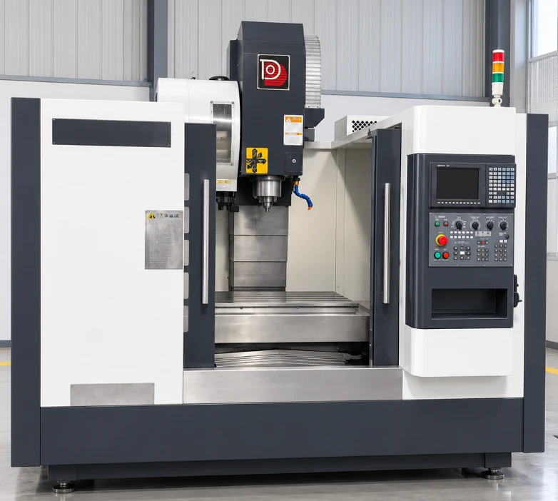
CNC machining forms the tooling components that carry the part geometry. It sits within a wider route of EDM, grinding, fitting and molding trials. The final check is how the assembled mold produces the agreed part.

Four sliders must release.
And return to the right place.
Our zero-draft enclosure case required four lateral sliders and an exterior without conspicuous junction lines. That puts the mold’s moving interfaces at the center of the tooling discussion: position, contact, support and the finished visible surface.
The same project included a recommendation for peripheral ribs around the mating panel. The mold and the assembled part therefore had to be considered together.
Follow the enclosure decisions ↗


Toolroom and molding photographs show the manufacturing environment. The enclosure case photographs show the specific molded product.
The feature sets
the inspection priority.
Our molded examples connect toolmaking to the part that reaches your assembly. We agree the important features with you, so appearance checks and functional checks have a clear purpose.
Openings and their edges
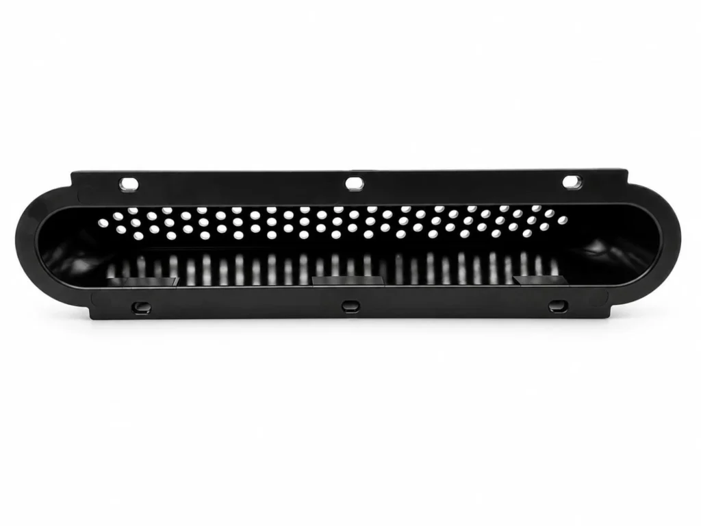
On a perforated cover, define acceptable flash and surface marks alongside the mounting fit.
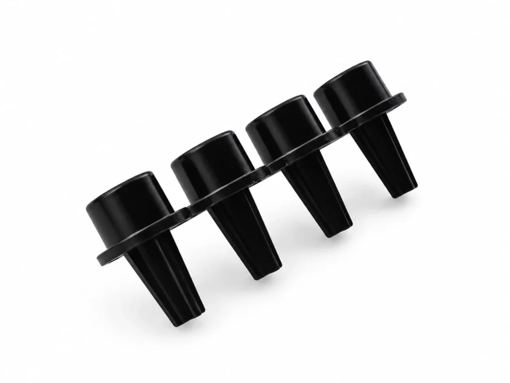
Stems and installed movement
On a button carrier, review the locating references, gate finish and motion in the assembled product.
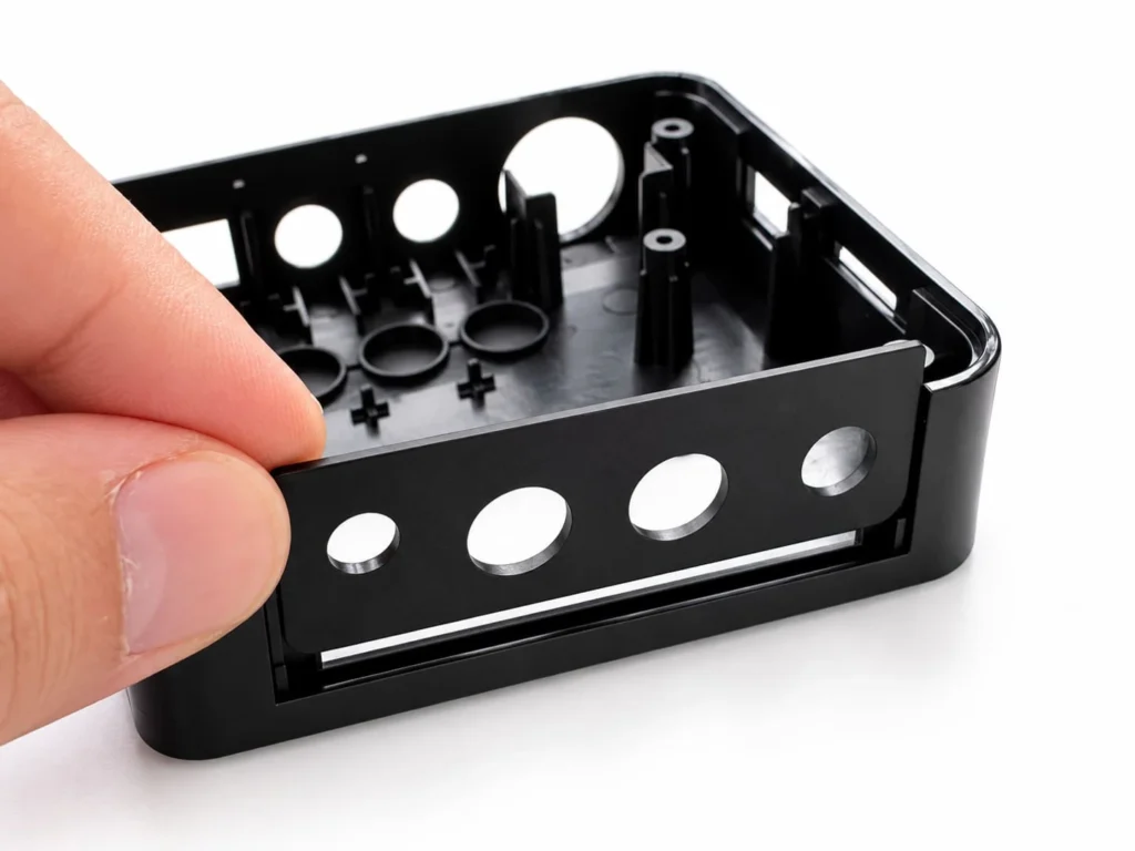
Panel position and closing fit
On a housing, compare the accepted sample with the mating panel, board and connectors.
A tool that makes your part.
A supply plan that fits your business.
Send your current design, quantity outlook and the interfaces that matter.
Material and surface
are manufacturing decisions.
The mold must do more than reproduce a shape. Soft contact regions, a rigid locating interface and a subtle appearance finish each introduce their own tooling and production questions.

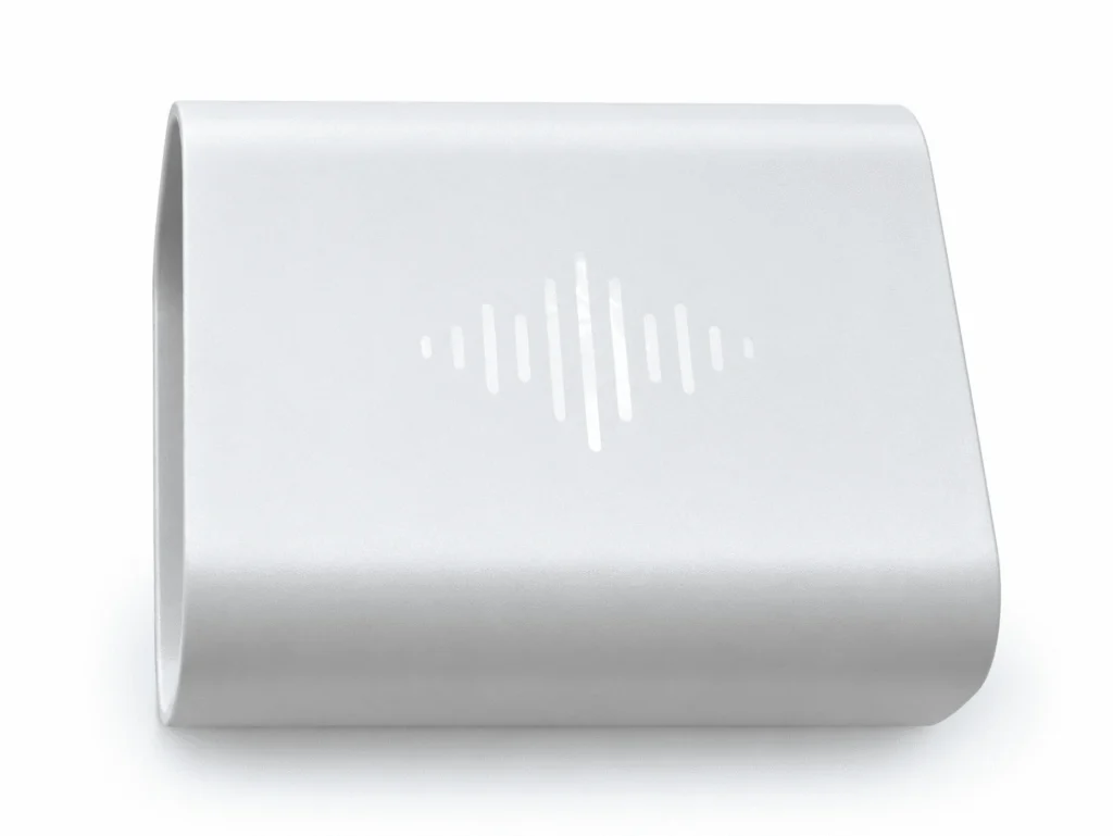
Virgin resin purchasing
First-grade virgin material is our standard. We do not use recycled or reprocessed feedstock to lower the price.
Tooling for continued use
Quality steel and adequate mold structure remain part of the build. We do not undersize the tool simply to cut the initial quote.
Owner-led coordination
The factory owner manages the project across tooling and production, keeping decisions and problem resolution direct.
Define acceptance
beyond the first molded sample.
A large ribbed shell
Confirm equipment fit, mounting datums and any downstream coating route before freezing the mold. A successful fill does not establish finished-assembly acceptance.
Ribs, equipment fit and post-process checks ↗A long curved component
Connect cooling and ejection decisions to the profile and multi-point engagement after stabilization. Define the trial-run checks before repeat supply.
Profile and assembly validation ↗