Start with the main
opening direction.
Identify which surfaces are formed by the main mold halves and whether the proposed geometry obstructs release in that direction. A side feature may require another motion if it cannot be formed and released by the main arrangement.
That is why the same-looking opening can lead to different tooling discussions on different parts. The parting arrangement and the surrounding geometry matter, not only the name “side hole.”
Ask which feature requires the side movement, what forms it, and whether the proposed alternative can still satisfy the product requirements.
What does the opening
do for the product?
Locates or supports
A connector or inserted component may rely on the closed edge. An opening to the parting edge could change that support.
Controls appearance
The visible boundary, seam or exposed opening may be part of the product's appearance requirement.
Controls access
Tool access, cable routing and the assembly sequence can constrain the size and shape of an opening.
Works with another part
A second housing component may complete the opening, but its position and fit must be part of the review.
Three routes to compare.
| Route | Why consider it? | What could prevent it? |
|---|---|---|
| Keep the feature; use a side action if required. | Preserves the required opening and its relationship to other components. | Tool construction, available motion and project cost/timing need review. |
| Extend or reshape the opening. | May permit a different forming and release arrangement. | The interface, visible edge, support or protection requirement may not allow the change. |
| Reconsider the split between mating parts. | May change how the opening is formed within the product assembly. | Seam position, assembly, locating features and both part designs could change. |
Compare the complete consequences. A simpler tool arrangement can be a poor choice if it weakens a required interface or creates an unacceptable visible seam.
A closed side port.
A direction-specific draft.
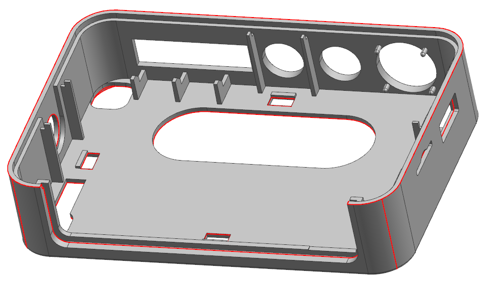
This enclosure combines side interfaces with internal ribs and visible outside walls. The supplied review proposes four side actions. Keeping a closed port may be the correct decision when its edge supports or locates a mating component; removing a slide is not a useful objective if the product interface is lost.
Two upper-cover reviews make the direction issue concrete. One proposes 1° at identified side-hole surfaces; another proposes 3° in the slide direction. Those are proposals for their respective geometries, not interchangeable draft rules. Main mold-opening draft does not resolve a surface that releases along another axis.
Mark the required connector opening and its datum first. Establish the parting arrangement and side-core travel. Then identify which surfaces may receive draft without moving the functional boundary. Check scuffing risk and the accepted visible edge together.
Pre-tooling reference: upper-cover DFM: H6 sheet 11 and ZPT sheets 3, 8 and 11. Engineering review by CustoMold.
A grille hole is also
a tool shutoff decision.
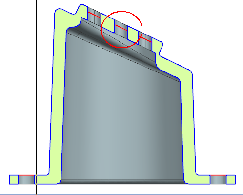

The perforated-cover report flags flash risk where tool surfaces shut off around the openings and proposes changes to the hole section and draft. A separate sheet asks the customer to confirm that the openings are elliptical. Tooling convenience cannot silently redefine the front-face pattern.
- Confirm the intended opening. Establish the front-view shape, pattern and functional clearance. An ellipse in the model may be intentional.
- Review the steel contact. Compare the proposed shutoff section with available tool steel, release direction and the actual geometry. The illustrated dimensions belong to this proposal.
- Define the part acceptance. Agree where flash is unacceptable, what appearance reference applies and how the openings will be checked after sampling. Keep those requirements when maintaining the tool.
Where this fits: speaker grilles, vented covers and visible perforated panels whose opening pattern and clean edges must survive manufacturing decisions.
Pre-tooling reference: perforated-cover DFM, sheets 14–15. Engineering review by CustoMold.
Sometimes the right answer
is a coordinated slide system.
The cartridge housing has internal and external restrictions that must release without losing its three-path interface. Our redesigned mold combines internal and external slides with angled withdrawal on the core side. One integrated mold replaced the customer's earlier two-mold approach and is now in ongoing production.


The judgment is not “use fewer slides at any cost.” It is whether the required geometry, release sequence, travel clearances and working-position support can be made compatible. A moving insert must both clear the molded feature and return accurately for the next cycle.
Follow the complete mold redesignBring these inputs
to the tooling discussion.
- Current enclosure and relevant mating CAD.
- The purpose of the opening and the component that uses it.
- Which faces, edges and dimensions may change.
- Appearance, protection and assembly requirements.
- The quantity outlook and the current tooling proposal.
A useful conclusion is a recorded choice with its conditions, not a universal rule about avoiding slides.

