A DFM report is useful when
you can act on it.
A highlighted face or an arrow can point to a manufacturing concern. It does not, by itself, explain whether the proposed change is acceptable for the product.
What needs to change, what requirement could it affect, and what must be confirmed before that change can be approved?
For a tooling and parts project, review geometry alongside material, appearance and assembly requirements. Tie comments to a specific CAD revision. Separate a manufacturing proposal from a customer-approved design change.

Four things to look for in each issue.
- Location: the exact feature and the file revision being reviewed.
- Reason: the molding, tool-release or assembly concern.
- Proposal: the intended change and the parts it affects.
- Decision: what information or approval is still needed.
A boss-wall change can
become an assembly decision.
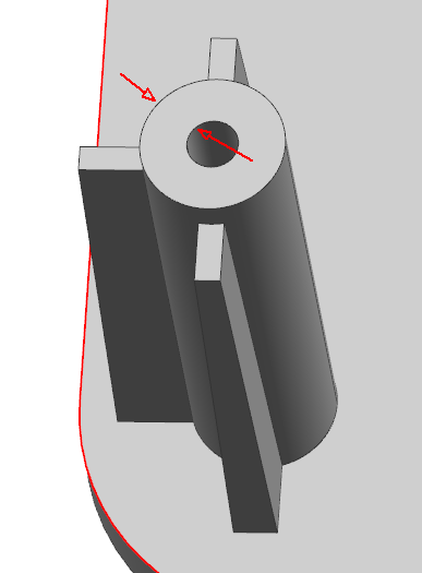
The supplied decorative-cover review provides a useful example: choosing how to change a local wall depends on the PCB and screw definition. The discussion cannot be completed from the isolated plastic feature alone.
Boss-wall changes depend on screw engagement and PCB clearance
The PCB and screw definition must be confirmed before choosing which boss dimension to change. This explanation uses the supplied report; the original CAD assembly and a strength test were not available.
The supplier identifies a local boss-wall thickness concern and connects the choice of modifying the inner hole or outer diameter to the PCB and screw requirements.
Supplier proposal: determine the appropriate inner-hole or outer-diameter change after the PCB and screw definition is confirmed. CustoMold discussion: compare fastening engagement, board location and surrounding clearance before approving a revision.
Supplier-provided decorative-cover DFM, pre-tooling stage. No trial or production result is included.
The important distinction is between reducing material in a feature and preserving the job that feature performs. The screw interface, surrounding clearance and locating function can constrain different dimensions.
Compare options by what
they change in the product.
| Discussion option | What it changes | What to confirm |
|---|---|---|
| Modify the inner hole | The screw interface and the local wall. | Fastener definition, engagement requirement and fastening method. |
| Modify the outer diameter | The outside envelope and any locating contact. | PCB relationship, required support and nearby clearance. |
| Revisit the feature arrangement | Potentially the molded part and its mating components. | Which parts may change, who approves them and the tooling/assembly impact. |
This comparison explains decision conditions. It does not prescribe a universal boss dimension or establish a validated redesign.
One wall target. Two very different interfaces.
The source marks a 4.5 mm outside diameter and a 1.6 mm hole: a nominal concentric wall of (4.5 − 1.6) / 2 = 1.45 mm. It proposes a 1.2 mm wall, while asking whether the inner or outer diameter can change.
In that simplified section, keeping the outside diameter would make the hole 2.1 mm; keeping the hole would make the outside diameter 4.0 mm. These are arithmetic illustrations, not approved CAD dimensions. The first changes screw engagement; the second changes the surrounding support envelope. Neither can be selected just because the wall becomes thinner.
Our review: identify the screw and fastening method, PCB location and support, then decide which interface is allowed to move. Agree the assembly and fastening checks before releasing the revision.
The same reasoning applies beyond bosses.
A proposal for relief around a gate area may involve a second component. A side-opening change may affect connector support. A gate-location change may alter more than the visible gate mark. Follow the affected function beyond the local highlight.
The ejection problem is in one cover.
The change is in the other.
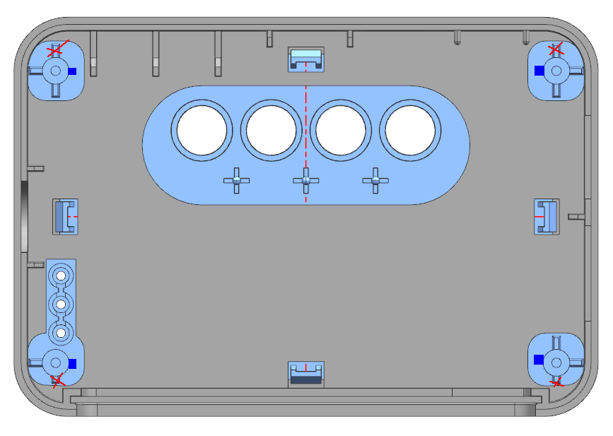
The report states that the lower cover has insufficient room for ejectors at four corners. Its proposal moves ribs on the decorative cover from the red positions to the blue positions. Reviewing either plastic part alone would miss why the other part needs to change.
Sheet 6 proposes reducing four ribs by 0.2 mm because they are too close to the lower cover. Sheet 10 proposes moving corner ribs for ejector space. Clearance and tool access are different constraints; one dimensional adjustment does not automatically resolve both.
Identify whether each rib locates, supports or stiffens the assembly. Check the new position against the lower cover, internal components and the intended ejector layout. Both component revisions belong in the review.
The tooling review must confirm usable ejector space. The assembled sample review must confirm closing fit, support and visible deformation at the corners. A revised rib position is a proposal until those requirements are accepted.
Where this fits your product: paired enclosure halves, decorative covers over structural housings, and compact assemblies where internal ribs compete with tooling access.
Pre-tooling reference: decorative-cover DFM, sheets 6 and 10. Engineering review by CustoMold.
The precision requirement
belongs to an interface.
In our cartridge project, three narrow outlets must align with a bonded chip while keeping the ink paths separate. The approximately 0.01–0.02 mm requirement at critical features is therefore a question about datums, hole position, spacing and interface height—not simply a request to make every dimension tighter.
Product requirement: open, separated paths that align with the chip.
Engineering decision: preserve those functions while coordinating internal and external slides and angled core-side withdrawal.
Implemented outcome: the customer's two-mold approach was redesigned into one mold, built and placed into continuing injection production.
For a new part, identify the mating component and the acceptance method before treating a tolerance callout as a complete manufacturing specification.
See the full production caseKeep a short decision record.
The record should make it possible for another person to identify the approved version without reconstructing a long email conversation.
Boss-wall geometry at the PCB fastening location.
Part / revision / marked view
Preserve the fastening and board-location function.
Customer product requirement
Confirm screw definition and mating geometry.
Information required
Pending technical confirmation.
Owner / next action / revision
Match the review to
the stage of the project.
Identify the questions.
Use the available design to discuss feasibility, quotation assumptions and missing information. Keep unresolved material or assembly requirements visible.
Close the agreed changes.
Provide the current part and relevant mating files. Reflect approved changes in a controlled revision and distinguish accepted items from pending ones.
After tooling, samples are reviewed against the agreed requirements. A DFM proposal is part of preparation; it does not establish a sample acceptance or production result.
See the complete tooling and parts process ↗